Build guide · Manual V1.1.1
XP2 build guide
The official MMC XP2 manual as a web page: parts lists, design notes and all 37 assembly steps.
Before you start
- Print every part in the printed parts lists below and get the shopping list ready before you start.
- Each step builds one sub-assembly. Keep them aside until the final assembly, as the notes say.
- The download includes an interactive 3D PDF of the chassis. Open it in Adobe Acrobat Reader to rotate and explode the model while you build.
- Use the PDF if you prefer to build offline: MMC_XP2_Chassis_Manual_V1.1.1.pdf.
You can
- Print and use the parts for private use, in unlimited quantity.
- Share photos of your prints on social networks or websites.
You can't
- Commercial use or public sharing of the 3D model.
- Modifying or adapting the model for public sharing or sale.
- Distributing, selling, donating or exchanging the digital files.
Bill of materials
Printed parts, black 23 lines
| Qty | Part | Description |
|---|---|---|
| 11 | SPCR_2MM | 2mm Spacer |
| 1 | SPCR-3MM | 3mm Spacer |
| 1 | XP2-001 | Lower Deck |
| 1 | XP2-003-1 | Front LCA Left |
| 1 | XP2-003-2 | Front LCA Right |
| 2 | XP2-006 | Front UCA Right and Left |
| 2 | XP2-008 | Front Fixed-length Push-rod |
| 1 | XP2-1010 | Upper Deck |
| 1 | XP2-1230-1 | Rear LCA Right |
| 1 | XP2-1230-2 | Rear LCA Left |
| 1 | XP2-1231-1 | Rear UCA Right |
| 1 | XP2-1231-2 | Rear UCA Left |
| 2 | XP2-1234 | Rear Traction Fixed-length Arm |
| 2 | XP2-1236 | Rear Traction Fixed-length Arm |
| 2 | XP2-1237 | Rear Traction Fixed-length Arm |
| 1 | XP2-1244 | Rear Heave Spacer |
| 1 | XP2-1311 | Servo Fixed-length Actuator |
| 1 | XP2-1312 | Steering Lower Spacer |
| 1 | XP2-1313 | Steering Upper Spacer |
| 2 | XP2-1315 | Fixed-length Steering Rods |
| 1 | XP2-1401-1 | Rear Bulkhead Right |
| 1 | XP2-1401-2 | Rear BulkHead Left |
| 1 | XP2-1418 | Adjustable Motor Support |
Printed parts, colour 31 lines
| Qty | Part | Description |
|---|---|---|
| 4 | RPF1_Wheel | 26mm Wheel (Enkei RPF1 replica) |
| 4 | SPCR_1 (5mm) | 1mm Spacer (5mm diameter) |
| 2 | SPCR_3.5 (5mm) | 3.5mm Spacer (5mm diameter) |
| 1 | XP2-002 | Front Subframe |
| 1 | XP2-005 | Front UCA and Caster Adjustability Support |
| 1 | XP2-007 | Front Suspension Rocker Arm |
| 1 | XP2-009 | Flex plate |
| 2 | XP2-036 | Front Suspension Spacer |
| 2 | XP2-1002 | Battery Support |
| 1 | XP2-1003 | Body post front magnet support |
| 1 | XP2-1004 | ESC Support |
| 1 | XP2-1014-1 | Front Knuckle Right |
| 1 | XP2-1014-2 | Front Knuckle Left |
| 1 | XP2-1232-1 | Rear BellCrank Right |
| 1 | XP2-1232-2 | Rear BellCrank Left |
| 1 | XP2-1235-1 | Rear Knuckle Right |
| 1 | XP2-1235-2 | Rear Knuckle Left |
| 1 | XP2-1241 | Rear Heave Crank |
| 1 | XP2-1242 | Rear Heave Rocker |
| 1 | XP2-1309 | Steering Lever Arm |
| 1 | XP2-1310 | Steering Wiper |
| 1 | XP2-1417 | Motor Support Spacer |
| 1 | XP2-1421 | 14T Belt Pulley |
| 1 | XP2-1422 | Main Shaft Cover |
| 1 | XP2-1423 | 38T Belt Pulley First Stage |
| 1 | XP2-1425 | 20T Belt Pulley |
| 1 | XP2-1426 | Secondary Shaft End Cap |
| 1 | XP2-1428 | 14T Belt Pulley |
| 1 | XP2-1429 | 38T Belt Conversion for Rhino C-LSD / YD2 Diff |
| 1 | XP2-1430 | Press-fitted 14T Pinion to 14T Belt Pulley Adapter |
| 1 | XP2-1440 | Rear Subframe |
Shopping list 37 lines
| Qty | Part | Description |
|---|---|---|
| 1 | 14T_PINION | Standard 14T 48p pinion |
| 1 | 540_MOTOR.3 | Standard 540 Size Motor |
| 56 | BallJoint_4.8mm | 4.8mm BallJoint (6mm thread), see recommended parts |
| 1 | Battery | "Shorty" type battery |
| 9 | BB-10X15X4.4 | Ball Bearing, OD: 15mm, ID: 10mm, WIDTH: 4mm |
| 17 | BB-5X9X3.1 | Ball Bearing, OD: 9mm, ID: 5mm, WIDTH: 3mm |
| 1 | Differential | Rhino C-LSD Differential (RR-600) or Yokomo Standard Differential (Y2-500GSAA) |
| 1 | HTD3MBELT_42T (red.) | 42T HTD3M belt (3 or 4 mm) |
| 2 | HTD3MBELT_52T (diff) | 52T HTD3M belt (3 or 4 mm) |
| 2 | ISO10642 M3x10 | CounterSunk ISO10642 M3x10 Screw |
| 2 | ISO10642 M3x6 | CounterSunk ISO10642 M3x6 Screw |
| 34 | ISO10642 M3x8 | CounterSunk ISO10642 M3x8 Screw |
| 4 | ISO10642 M4x10 | ISO10642 M4x10 Countersunk screw |
| 5 | ISO4026-M3x10 | M3x10 hexagon socket set screw ISO4026 |
| 2 | ISO7380 M3x10 | ButtonHead ISO7380 M3x10 Screw |
| 4 | ISO7380 M3x12 | ButtonHead ISO7380 M3x12 Screw |
| 4 | ISO7380 M3x16 | ButtonHead ISO7380 M3x16 Screw |
| 4 | ISO7380 M3x20 | ButtonHead ISO7380 M3x20 Screw |
| 5 | ISO7380 M3x6 | ButtonHead ISO7380 M3x6 Screw |
| 14 | ISO7380 M3x8 | ButtonHead M3x8 screw |
| 1 | LHN-45 | Long Hex Nut M4 (45mm) |
| 1 | LHN-60 | Long Hex Nut M4 (60mm) |
| 7 | RN-10 | Round Nut M3 (10mm) |
| 6 | RN-15 | Round Nut M3 (15mm) |
| 3 | RN-20 | Round Nut M3 (20mm) |
| 2 | RN-25 | Round Nut M3 (20mm) |
| 2 | RN-30 | Round Nut M3 (30mm) |
| 4 | RN-35 | Round Nut M3 (35mm) |
| 1 | Servo | Low Profile type Servo |
| 1 | ServoHorn | Standard Servo Horn (Metal) |
| 4 | Shock_Bottom | 55mm Shock Absorbers (Bottom Part) |
| 4 | Shock_Top | 55mm Shock Absorber (Top Part) |
| 27 | TI-4 | Brass Threaded Insert (M3x4x4,5) |
| 70 | TI-6 | Brass Threaded Insert (M3x6x4,5) |
| 4 | WHEEL_HEX | Wheel Hexagon |
| 2 | YOKOMO_47MMAXLE_2 | Yokomo 47/49mm Rear Axle (Yokomo Y2-010) |
| 2 | YOKOMO_FRONTAXLE | Yokomo Simple Front Axle, Yokomo YD-2 (Y2-010FAA) |
Recommended parts
Parts listed in the manual. Links go to third-party shops.
Design notes
Control arm lengths
The chassis comes with printable control arms. All of them can be swapped for conventional turnbuckles.
The idea is to reduce costs and give you a good starting point for the alignment.
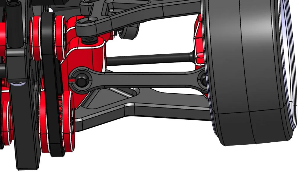
Front suspension
The front suspension is a standard double wishbone setup. The standard version has no camber or track width adjustment; optional parts are on the way.
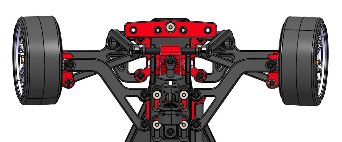
Its main feature is the mono-shock design. It stiffens the roll of the front of the chassis, acting as a sway bar, which translates into more front grip. The more roll the rear allows, the greater the front grip.
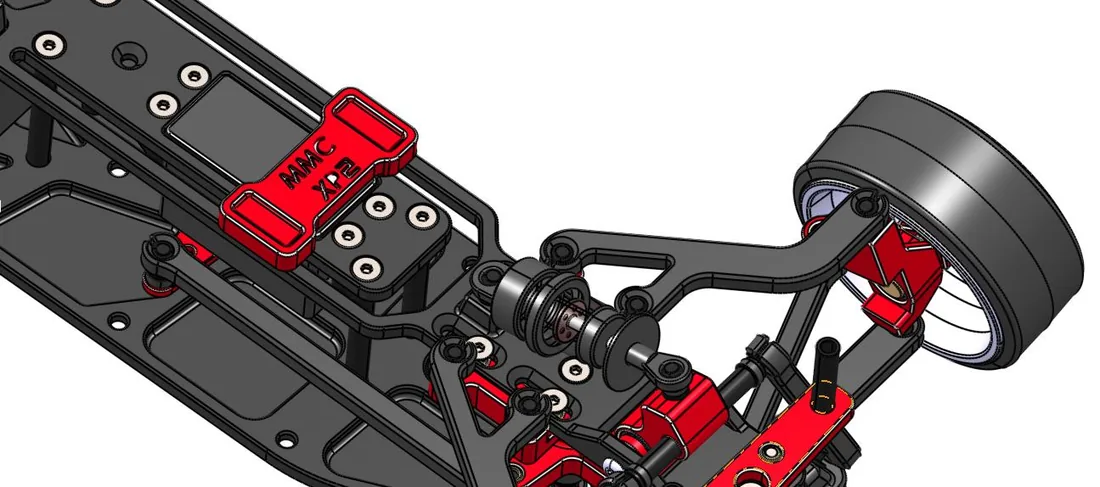
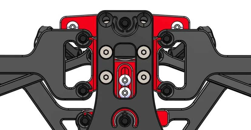
Flex slider
The slider acts as an anti-roll bar. Further forward means a stiffer chassis: the rear roll applies more force to the front. Further back means the rear roll is absorbed by the flex of the chassis, so the front is freer and less force is transferred.
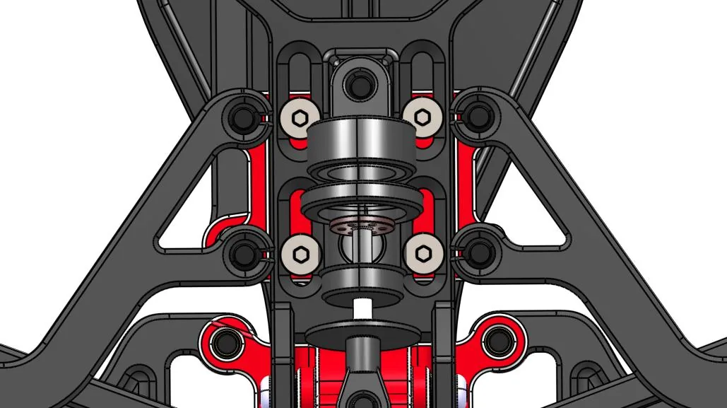
Caster and Ackerman
Move the upper control arms to adjust caster. Move the steering linkage to adjust Ackerman.
Assembly
-
Step 1: Front bell crank
XP2-1140· 20 parts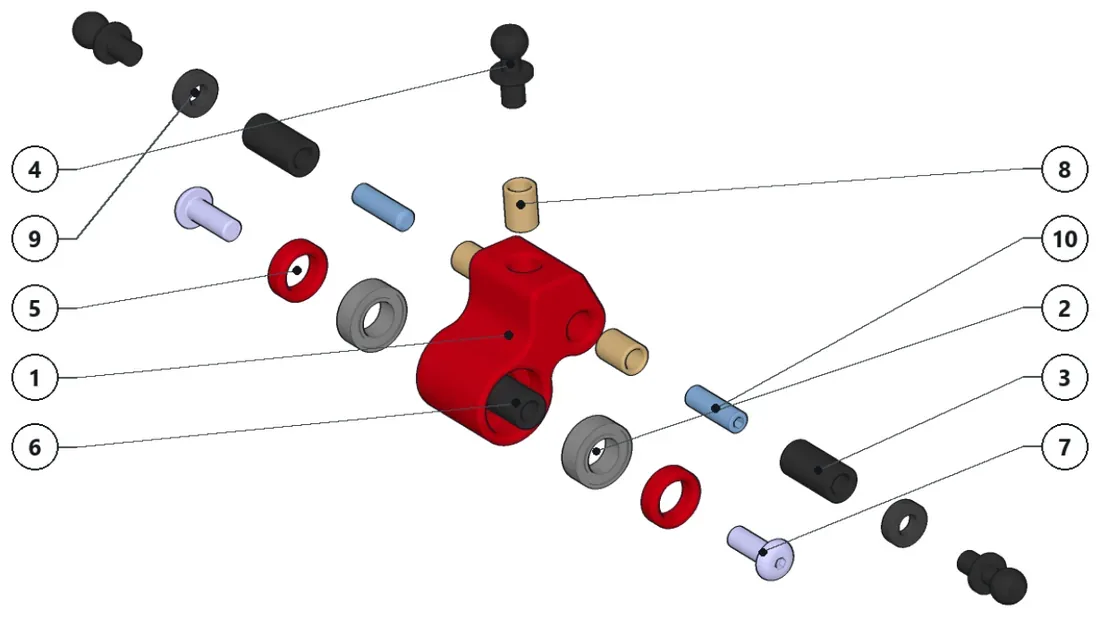
- Install threaded inserts.
- Press the bearings.
- Install the worm screws and the round nuts.
- Install spacers and ballstuds.
- The shaft may need to be filed down slightly to fit into the ball bearing.
Parts · numbers match the drawing
XP1-007×1BB-5X9X3×2RN-15×2Round Nut M3 (15mm)BallJoint_4.8mm×34.8mm BallJoint (6mm thread)XP1-036×2RN-20×1Round Nut M3 (20mm)ISO7380 M3x8×2ButtonHead M3x8 screwTI-6×3SPCR_2MM×22mm SpacerISO4026 M3x10Hex socket set screw M3x10
-
Step 2: Sub-assembly XP2-1020
4 parts — make 2 times
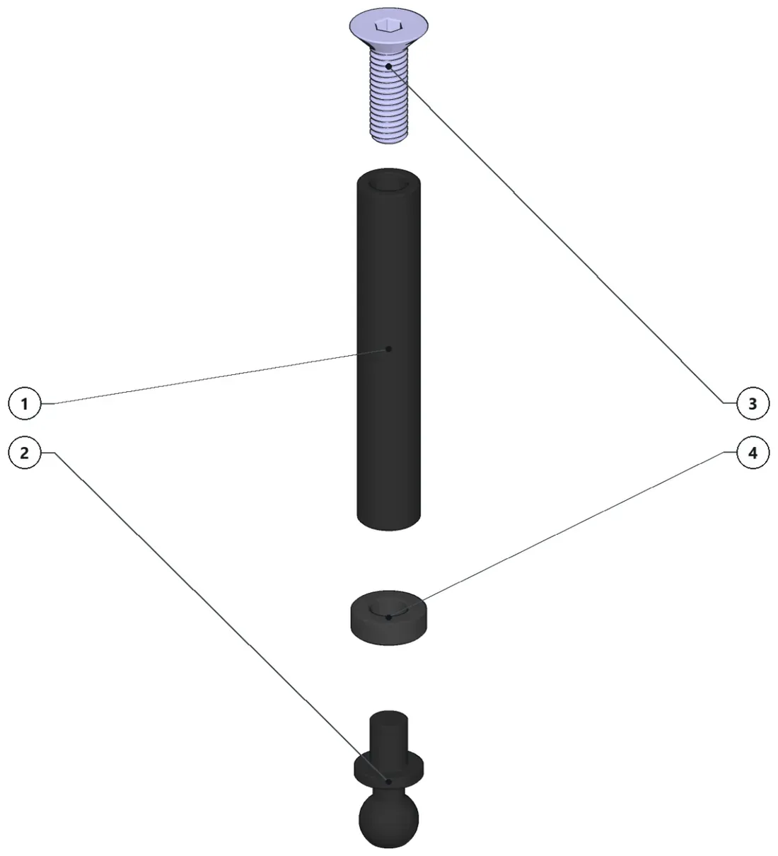
- Put together the round nut with the spacer and ballstud.
- Keep the screw to install later to the upper deck.
Parts · numbers match the drawing
RN-30×1Round Nut M3 (30mm)BallJoint_4.8mm×14.8mm BallJoint (6mm thread)ISO10642 M3x10Countersunk M3x10 screwSPCR_2MM×12mm Spacer
-
Step 3: Battery support
XP2-1003· 3 parts — make 2 times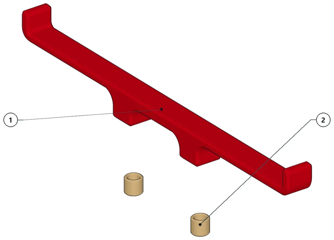
- Install threaded inserts.
Parts · numbers match the drawing
XP2-1002×1Battery SupportTI-4×2
-
Step 4: Sub-assembly XP2-1030
9 parts
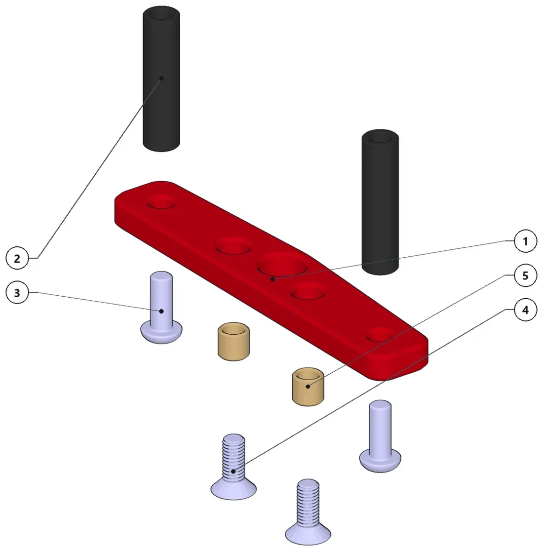
- Install threaded inserts.
- Bolt down the round nuts with the screws.
- Keep the two countersunk screws to assemble this sub-assembly to the chassis.
Parts · numbers match the drawing
XP2-1003×1Body post front magnet supportRN-20×2Round Nut M3 (20mm)ISO7380 M3x8×2ButtonHead M3x8 screwISO010642 M3x8×2CounterSunk ISO10642 M3x8…Th4×2
-
Step 5: Sub-assembly XP2-1040
5 parts
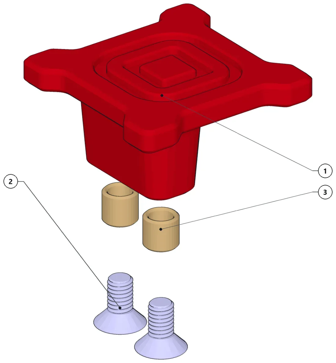
- Install the threaded inserts.
- Keep the countersunk screws to assemble this sub-assembly to the chassis.
Parts · numbers match the drawing
XP2-1004×1ESC Support1S010642 M3x6×2CounterSunk ISO10642 M3x6…TI-4×2
-
Step 6: Structural chassis
XP2-1000· 64 parts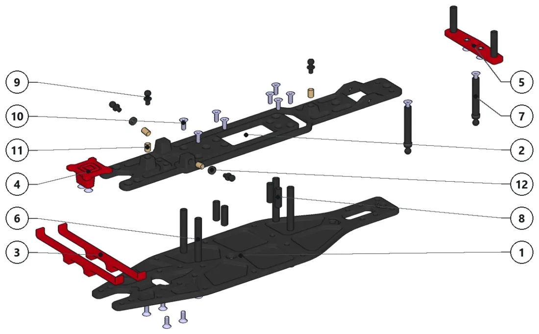
- Install the threaded inserts.
- Install the spacers and ballstuds.
- Pop in the XP2-1020 sub-assemblies to the lower deck.
- Bolt down all the round nuts and sub-assemblies.
Parts · numbers match the drawing
XP2-001×1Lower DeckXP2-1010×1Upper DeckXP2-1003_BatterySupport×2XP2-1040×1XP2-1030×1RN-35×4Round Nut M3 (35mm)XP2-1020×2RN-15×4Round Nut M3 (15mm)BallJoint_4.8mm×44.8mm BallJoint (6mm thread)1S010642 M3x8×16CounterSunk ISO10642 M3x8…TIl-6×4SPCR_2MM×22mm Spacer nN
-
Step 7: Sub-assembly XP2-1110
13 parts
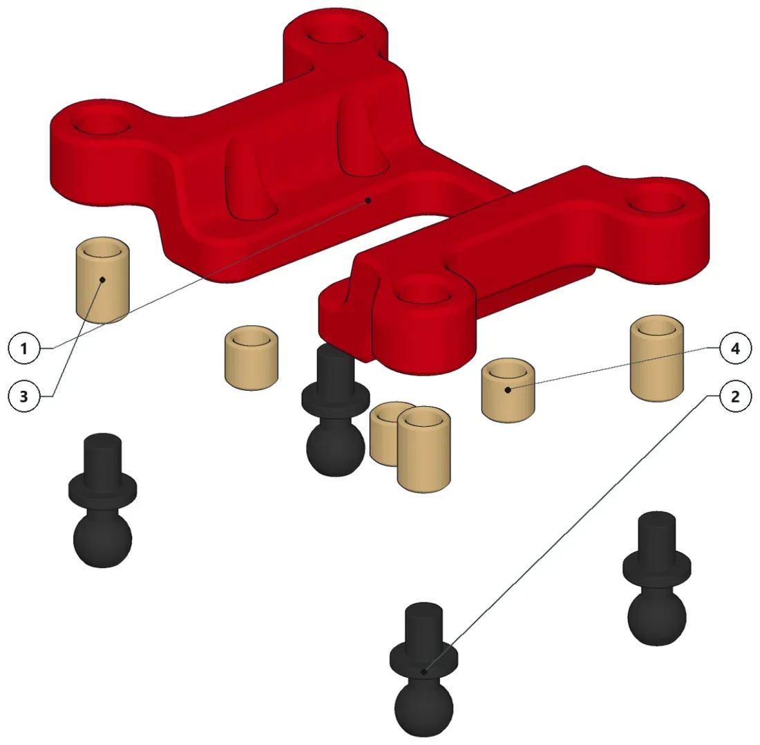
- Install the threaded inserts (outside are 6mm long, inside are 4mm long)
- Install the ballstuds.
Parts · numbers match the drawing
XP2-002×1Front SubframeBallJoint_4.8mm×44.8mm BallJoint (6mm thread)Th6×4TI-4×4
-
Step 8: Sub-assembly XP2-1120-1
3 parts
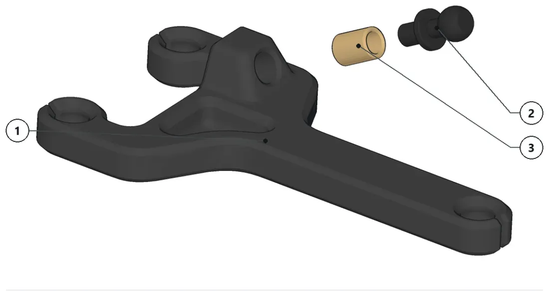
- Install the threaded insert.
- Install the ballstud.
Parts · numbers match the drawing
XP2-003-1×1Front LCA LeftBallJoint_4.8mm×14.8mm BallJoint (6mm thread)TIl-6×1
-
Step 9: Sub-assembly XP2-1120-2
3 parts
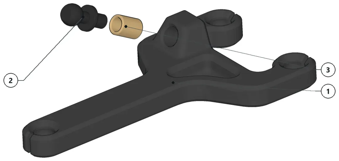
- Install the threaded insert.
- Install the ballstud.
Parts · numbers match the drawing
XP2-003-2×1Front LCA RightBallJoint_4.8mm×14.8mm BallJoint (6mm thread)TI-6×1
-
Step 10: Suspension front I
XP2-1100· 23 parts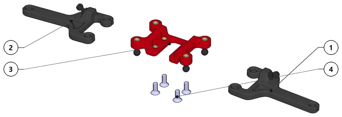
- Pop in the lower control arms to the ballstuds.
- Keep the countersunk screws to assemble this sub-assembly to the chassis.
Parts · numbers match the drawing
a XP2-1120-1×1XP2-1120-2×1XP2-1110×1ISO10642 M3x8×4CounterSunk ISO10642 M3x8…
-
Step 11: Sub-assembly XP2-1450-1
19 parts
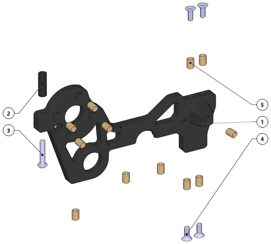
- Install all threaded inserts.
- Bolt down the rear round nut with the screw.
- Keep the countersunk screws to assemble this sub-assembly to the chassis.
Parts · numbers match the drawing
XP2-1401-1×1Rear Bulkhead RightRN-15×1Round Nut M3 (15mm)ISO7380 M3x16×1ButtonHead ISO7380 M3x16S…ISO10642 M3x8×4CounterSunk ISO10642 M3x8…TI-6×12
-
Step 12: Sub-assembly XP2-1409
8 parts
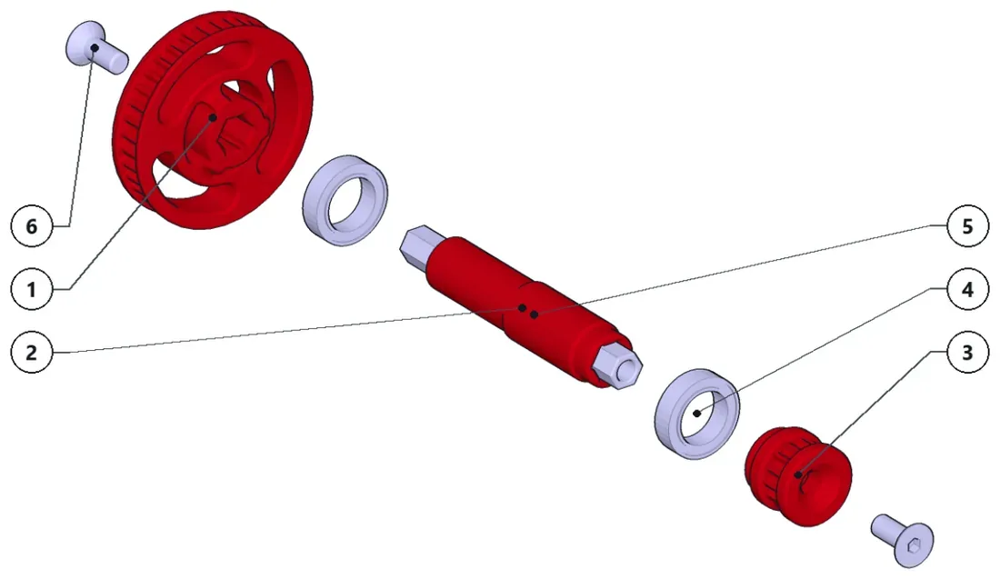
- Keep the pulleys unassembled for the next steps.
Parts · numbers match the drawing
XP1-023×1XP1-022×1XP1-021×1J BB-10X15X4×2LHN-60×1Long Hex Nut M4 (60mm)ISO10642 M4x10×2ISO10642 M4x10 Countersun…
-
Step 13: Sub-assembly XP2-1450-2
19 parts
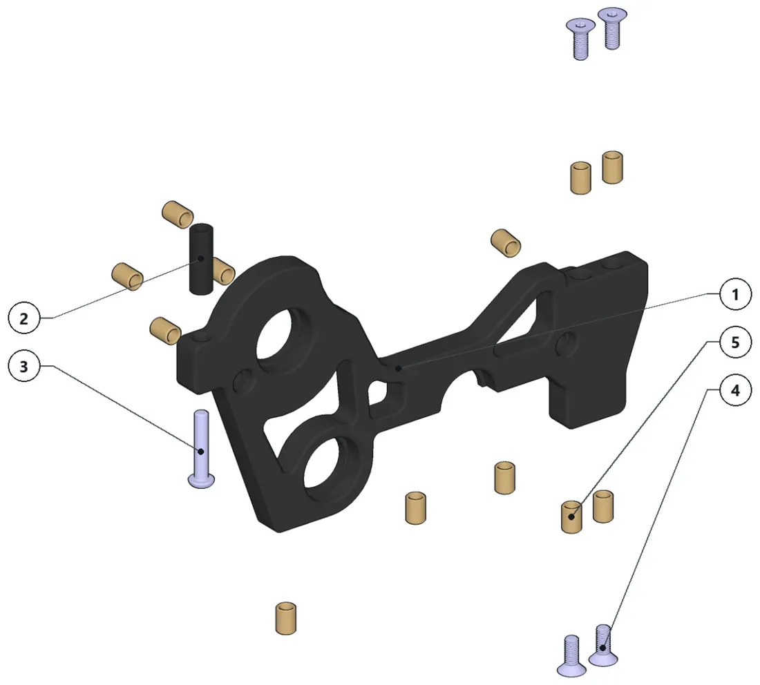
- Install all threaded inserts.
- Bolt down the rear round nut with the screw.
- Keep the countersunk screws to assemble this sub-assembly to the chassis.
Parts · numbers match the drawing
XP2-1401-1×1Rear Bulkhead RightRN-15×1Round Nut M3 (15mm)ISO7380 M3x16×1ButtonHead ISO7380 M3x16S…ISO10642 M3x8×4CounterSunk ISO10642 M3x8…TI-6×12
-
Step 14: Sub-assembly XP2-1410
8 parts
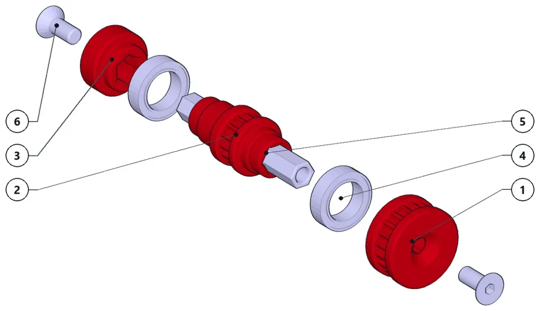
- Keep the pulleys unassembled for the next steps.
Parts · numbers match the drawing
XP1-025×1XP1-028×1XP1-026×1BB-10X15X4×2LHN-45×1Long Hex Nut M4 (45mm)ISO10642 M4x10×2ISO10642 M4x10 Countersun…
-
Step 15: Drive gear
2 parts
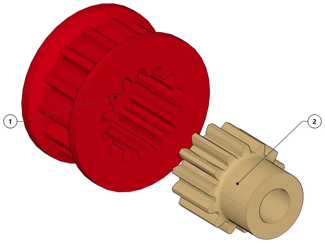
- Press fit the pinion to the pulley (you may need a vice)
Parts · numbers match the drawing
xp2-1430×1Press-fitted 14T Pinion to 14T Belt P..14T_PINION×1Standard 14T 48p pinion
-
Step 16: RDX spool
3 parts
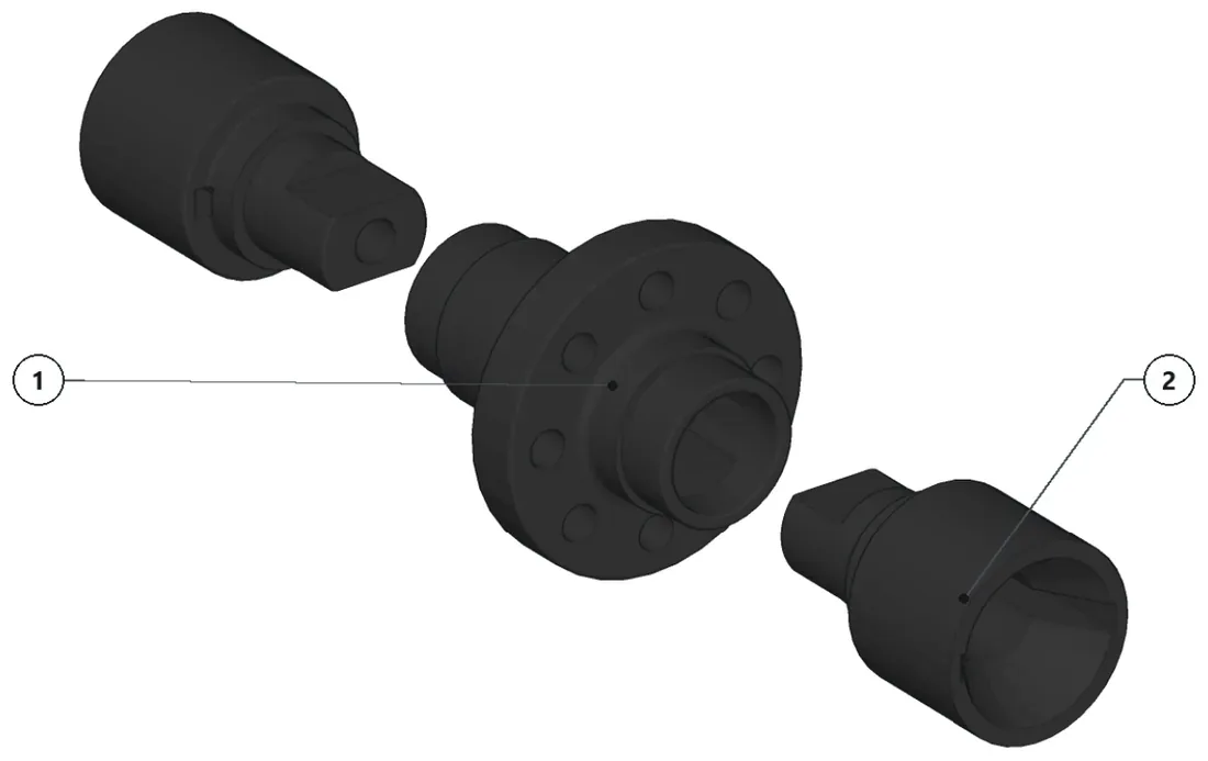
Parts · numbers match the drawing
SPOOL×1CUP×2
-
Step 17: Sub-assembly XP2-1411-RDX
10 parts
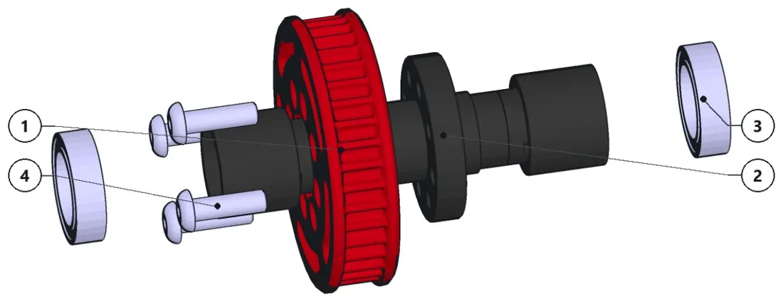
- Assemble the RDX spool (or yokomo/rhino/KKPIT diff) and screw the pulley to the diff.
- Install the bearings and then the end caps of the diff (RDX only).
Parts · numbers match the drawing
XP2-1412×1RDX SPOOL×1RDX SPOOLBB-10X15X4.4×2Ball Bearing - OD: 15mm, ID: 10…ISO7380 M3x10×4ButtonHead ISO7380 M3x10S…
-
Step 18: Drive train
XP2-1400· 82 parts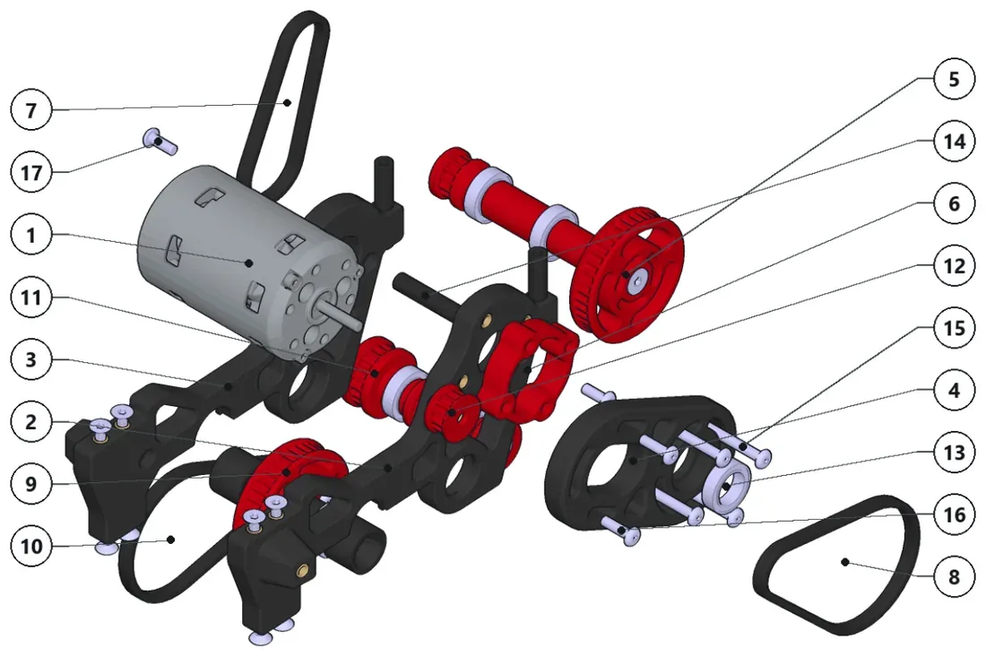
- Install the diff and XP2-1410 (without the outer pulleys) with the belt around them.
- Install XP2-1409 (without the outer pulleys).
- Once these three are in place, install all outer pulleys (except the XP2-022), belt and screws.
- Install the middle round nut spacer with the screws.
- Then install XP2-1417 and XP2-018 and its bearing and screws.
- Finally, install the motor and pulley with its belt.
Parts · numbers match the drawing
540_MOTOR×1XP2-1450-2×1XP2-1450-1×1XP1-018×1XP2-1409×1XP2-1417×1Motor Support SpacerHTD3MBELT_42T (red.)×142T HTD3M belt (3 orHTD3MBELT_S2T (diff)×152T HTD3M belt (3 or 4…XP2-1411-RDX×1HTD3MBELT_SOT (diff)×1XP2-1410×1DriveGear×1413) BB-10X15X4×1RN-25×1Round Nut M3 (20mm)ISO7380 M3x12×4ButtonHead ISO7380 M3x12S…ISO7380 M3x10×2ButtonHead ISO7380 M3x10 S…ISO7380 M3x8×2ButtonHead M3x8 screw
-
Step 19: Sub-assembly XP2-1210
25 parts
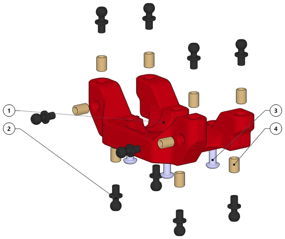
- Install all threaded inserts.
- Screw all the ballstuds.
- Keep the 4 screws to assemble this sub-assembly to the chassis.
Parts · numbers match the drawing
XP2-1440×1Rear SubframeBallJoint_4.8mm×104.8mm BallJoint (6mm thread)1807380 M3x12×4ButtonHead ISO7380 M3x12S…TI-6×10
-
Step 20: Sub-assembly XP2-1211-1
3 parts
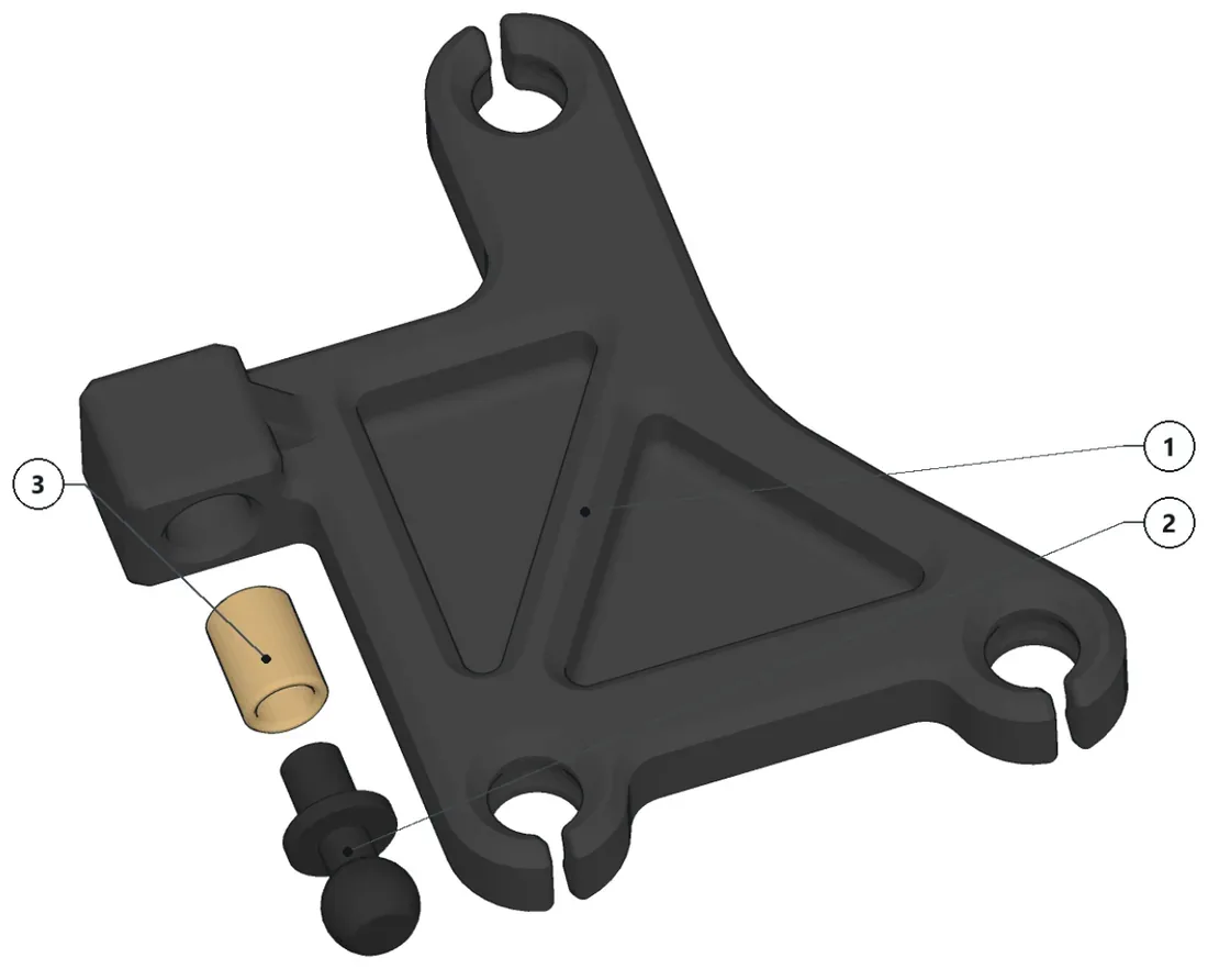
- Install the threaded insert and the ballstud.
Parts · numbers match the drawing
XP2-1231-1×1Rear UCA RightBallJoint_4.8mm×14.8mm BallJoint (6mm thread)TI-6×1
-
Step 21: Sub-assembly XP2-1211-2
3 parts
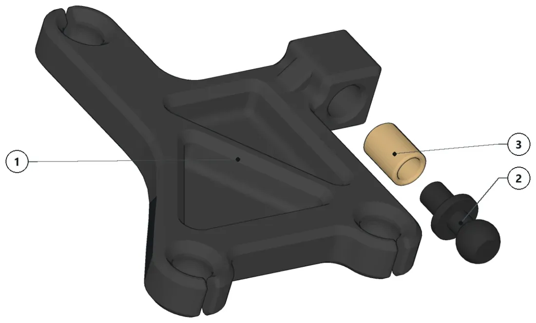
- Install the threaded insert and the ballstud.
Parts · numbers match the drawing
XP2-1231-2×1Rear UCA LeftBalUJoint_4.8mm×14.8mm BallJoint (6mm thread)TIl-6×1
-
Step 22: Rear knuckle (right)
XP2-1260-1· 10 parts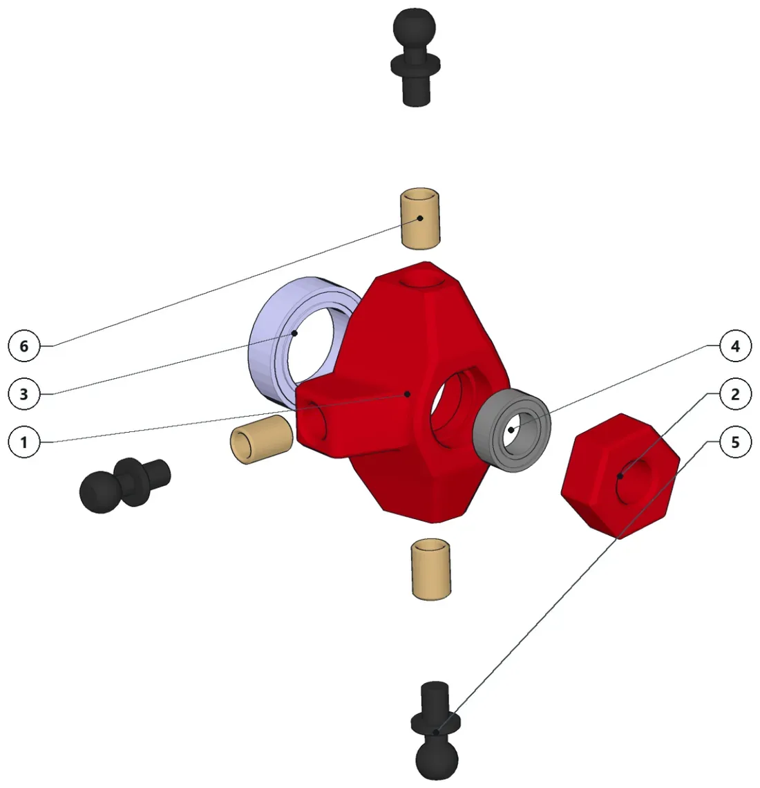
- Install all threaded inserts and ballstuds.
- Press the bearings.
Parts · numbers match the drawing
XP2-1235-1×1Rear Knuckle RightWHEEL_HEX×1Wheel HexagonBB-10X15X4×1BB-5X9X3.1×1Ball Bearing - OD: 9mm, ID: 5mm,…BallJoint_4.8mm×34.8mm BallJoint (6mm thread)TI-6×3
-
Step 23: Rear knuckle (left)
XP2-1260-2· 10 parts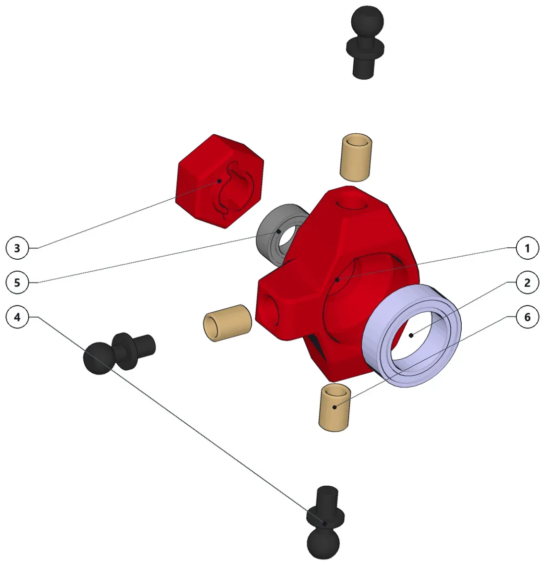
- Install all threaded inserts and ballstuds.
- Press the bearings.
Parts · numbers match the drawing
XP2-1235-1×1Rear Knuckle RightBB-10X15X4×1GB ) WHEEL_HEX×1Wheel HexagonA BallJoint_4.8mm×34.8mm BallJoint (6mm thread)BB-5X9X3.1×1Ball Bearing - OD: 9mm, ID: 5mm,…TI-6×3
-
Step 24: Suspension rear I
XP2-1200· 55 parts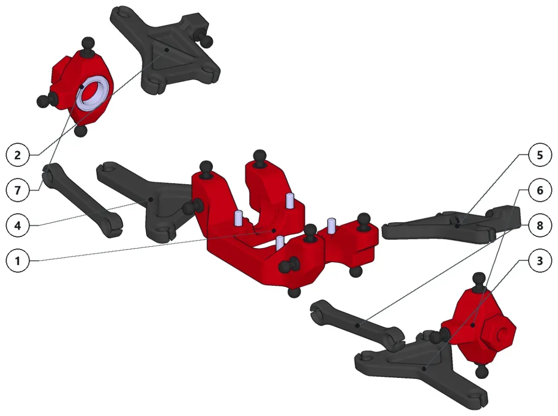
- Pop all the arms in place and keep the sub-assembly to install it to the chassis.
Parts · numbers match the drawing
XP2-1210×1XP2-1211-2×1XP2-1250-1×1XP2-1250-2×1XP2-1211-1×1XP2-1260-1_RearKnuckle_R×1XP2-1260-2_RearKnuckle_L×1XP2-1236×2Rear Traction Fixed-length Arm
-
Step 25: Rear bell crank
XP2-1240-1· 14 parts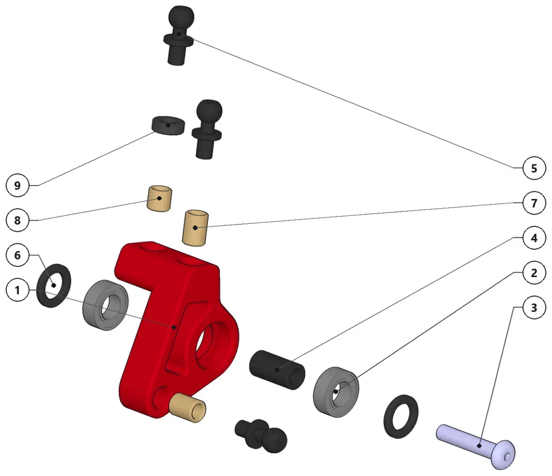
- Install all threaded inserts, spacers and ballstuds.
- Press the bearings.
- Ensure the round nut passes through the bearings, otherwise, a little file down might be needed.
- Make sure the screw passes through the entire length of the assembly with the outer spacers included.
Parts · numbers match the drawing
XP2-1232-1×1Rear BellCrank RightBB-5X9X3×2ISO7380 M3x16×1ButtonHead ISO7380 M3x16RN-10×1Round Nut M3 (10mm)BallJoint_4.8mm×34.8mm BallJoint (6mm thread)SPCR_1 (5mm)×21mm Spacer (5mm diameter)TI-6×2TI-4×1SPCR_2MM×12mm Spacer
-
Step 26: Rear heave crank
XP2-1240· 22 parts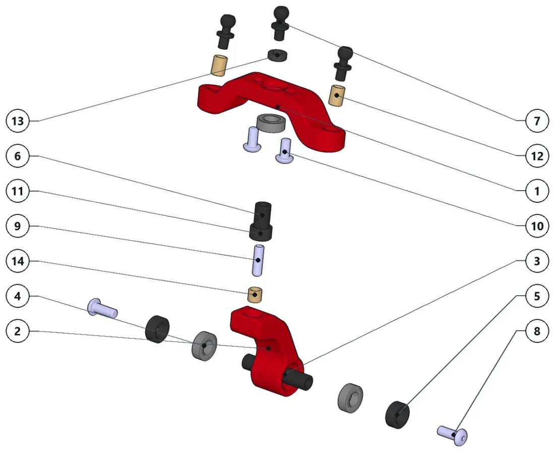
- Install all threaded inserts.
- Screw down the worm screw and the round nut to it.
- Press the two side bearings.
- Make sure the central round nut passes through the bearings, otherwise a little bit of file down might be needed.
- On the other side, install the central heave bearing and secure it with the two screws.
- Assemble the two sub-assemblies and install the central spacer and ballstud.
Parts · numbers match the drawing
XP2-1242×1Rear Heave RockerXP2-1241×1Rear Heave CrankRN-25×1Round Nut M3 (20mm)BB-SX9X3.1×3Ball Bearing - OD: 9mm, ID: 5mm,…SPCR_3.5 (5mm)×23.5mm Spacer (5mm diameter)RN-15×1Round Nut M3 (15mm)BalJoint_4.8mm×34.8mm BallJoint (6mm thread)ISO7380 M3x8×2ButtonHead M3x8 screw1S04026-M3x10×1M3x10 hexagon socket set scr…ISO7380 M3x6×2ButtonHead ISO7380 M3x6 Scr…XP2-1244×1Rear Heave SpacerTI-6×2SPCR_2MM×12mm SpacerTI-4×1
-
Step 27: Rear bell crank
XP2-1240-2· 14 parts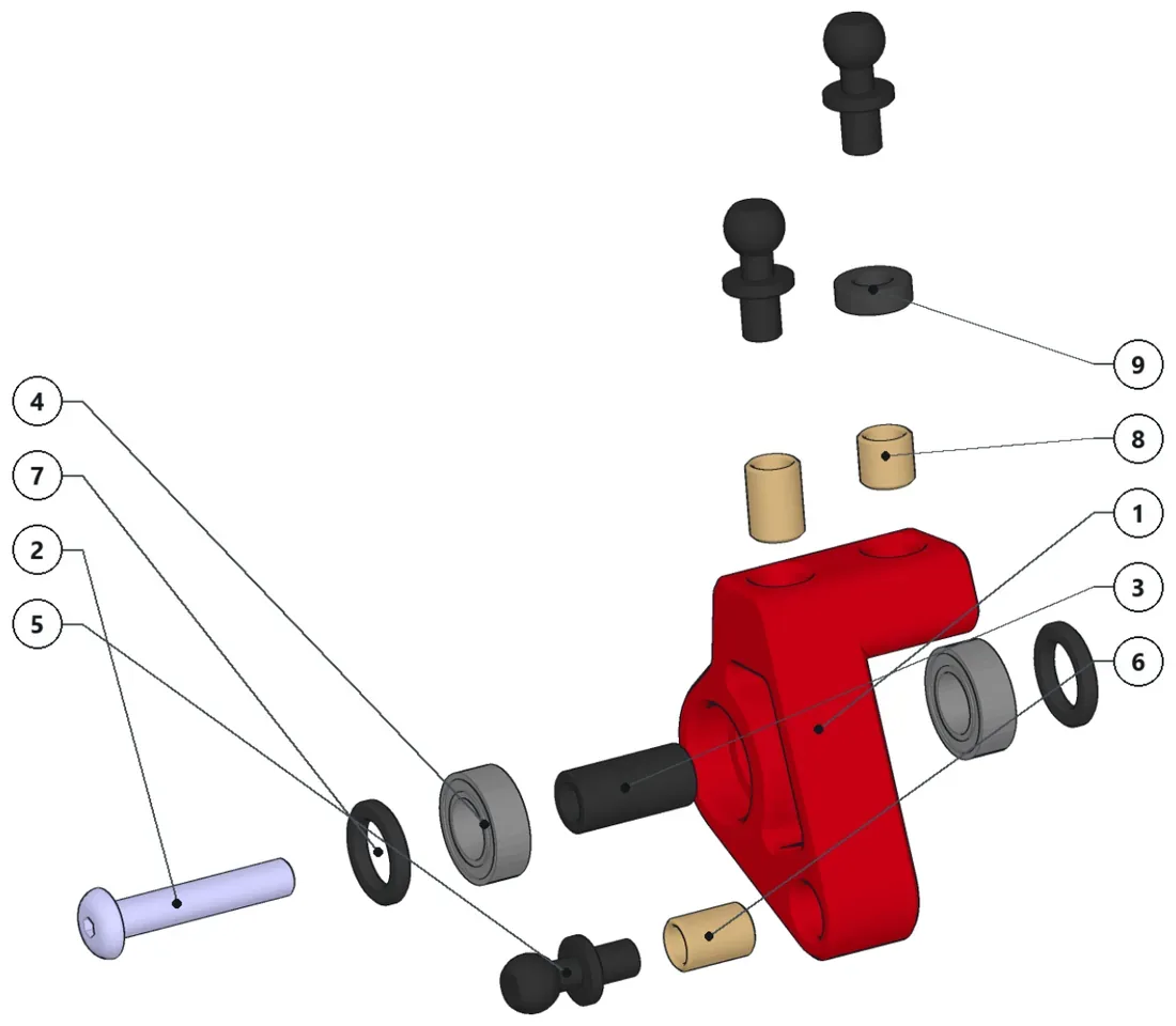
- Install all threaded inserts, spacers and ballstuds.
- Press the bearings.
- Ensure the round nut passes through the bearings, otherwise, a little file down might be needed.
- Make sure the screw passes through the entire length of the assembly with the outer spacers included.
Parts · numbers match the drawing
XP2-1232-2×1Rear BellCrank Left1807380 M3x16×1ButtonHead ISO7380 M3x16 S…RN-10×1Round Nut M3 (10mm)BB-SX9X3.1×2Ball Bearing - OD: 9mm, ID: Smm,…BallJoint_4.8mm×34.8mm BallJoint (6mm thread)TI-6×2SPCR_1 (5mm)×21mm Spacer (5mm diameter)TI-4×1SPCR_2MM×12mm Spacer
-
Step 28: Steering
XP2-1300· 18 parts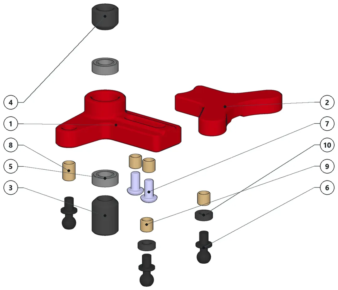
- Install all the 4mm threaded inserts to the XP2-1310 part.
- Install the remaining 6mm threaded insert to the XP1-009 part.
- Install the spacers and ballstuds to the steering wiper.
- Press the two bearings to the XP1-009 part.
- Keep the XP2-1312 and XP2-1313 spacers aside for the assembly to the chassis.
Parts · numbers match the drawing
XP1-009×1XP2-1310×1Steering WhiperXP2-1312×1Steering Lower SpacerXP2-1313×1Steering Upper SpacerBB-5X9X3.1×2Ball Bearing - OD: 9mm, ID: 5mm,…BallJoint_4.8mm×34.8mm BallJoint (6mm thread)ISO7380 M3x6×2ButtonHead ISO7380 M3x6 Scr…TI-6×1Th4×4SPCR_2MM×22mm Spacer
-
Step 29: Front knuckle (right)
XP2-1150-1· 13 parts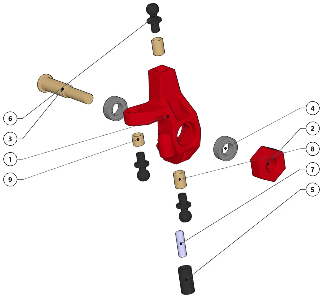
- Install all threaded inserts.
- Press the bearings.
- Install all ballstuds.
- Screw the worm screw and install the round nut (steering stopper)
- Install the Yokomo front axle through the bearings and install the wheel hexagon.
Parts · numbers match the drawing
XP1-014-1×1WHEEL_HEX×1Wheel HexagonYOKOMO_FRONTAXLE×1Yokomo Simple Front…BB-SX9X3.1×2Ball Bearing - OD: 9mm, ID: Smm,…RN-10×1Round Nut M3 (10mm)a BallJoint_4.8mm×34.8mm BallJoint (6mm thread)a ) 1S04026-M3x10×1M3x10 hexagon socket set scr…TI-6×2TI-4×1
-
Step 30: Front knuckle (left)
XP2-1150-2· 13 parts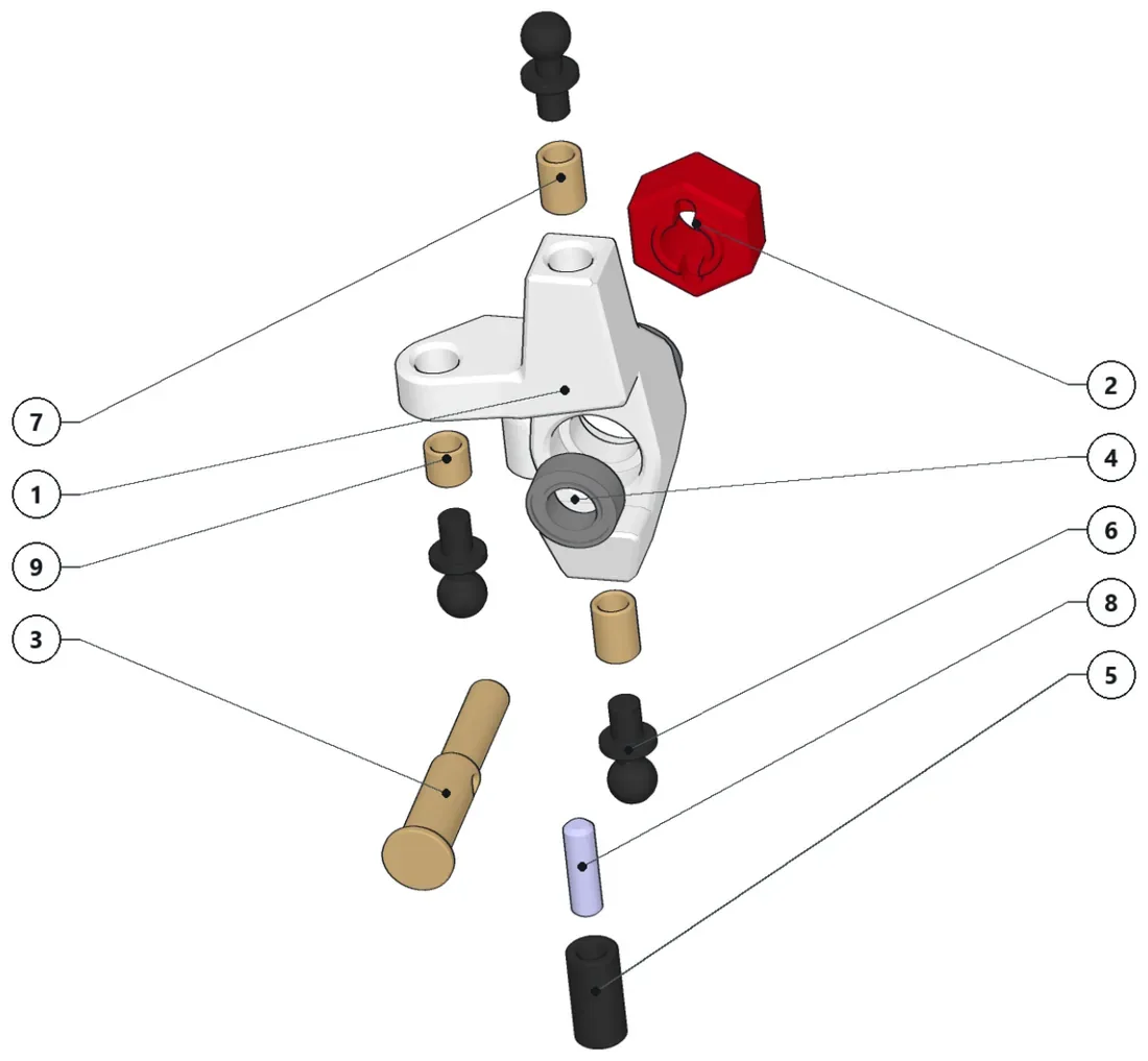
- Install all threaded inserts.
- Press the bearings.
- Install all ballstuds.
- Screw the worm screw and install the round nut (steering stopper)
- Install the Yokomo front axle through the bearings and install the wheel hexagon.
Parts · numbers match the drawing
XP2-1014-2×1Front Knuckle LeftWHEEL_HEX×1Wheel HexagonYOKOMO_FRONTAXLE×1Yokomo Simple FrontBB-5SX9X3.1×2Ball Bearing - OD: 9mm, ID: Smm, ..RN-10×1Round Nut M3 (10mm)BallJoint_4.8mm×34.8mm BallJoint (6mm thread)TI-6×2ISO04026-M3x10×1M3x10 hexagon socket set scr…TI-4×1
-
Step 31: Servo
XP2-1350· 9 parts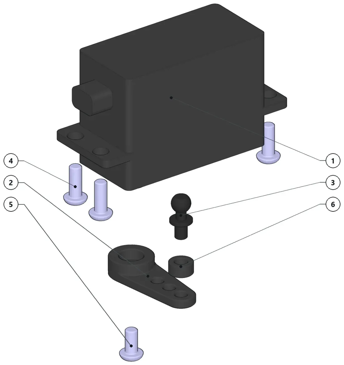
- Install the spacer and the ballstud to the servo horn in this position.
Parts · numbers match the drawing
Servo×1Low Profile type ServoServoHorn×1Standard Servo Horn (Metal)BallJoint 4.8mm×14.8mm BallJoint (6mm thread)ISO7380 M3x8×4ButtonHead M3x8 screwISO7380 M3x6×1ButtonHead ISO7380 M3xé6 Scr…SPCR-3MM×13mm Spacer
-
Step 32: Flex adjustment
XP2-1160· 5 parts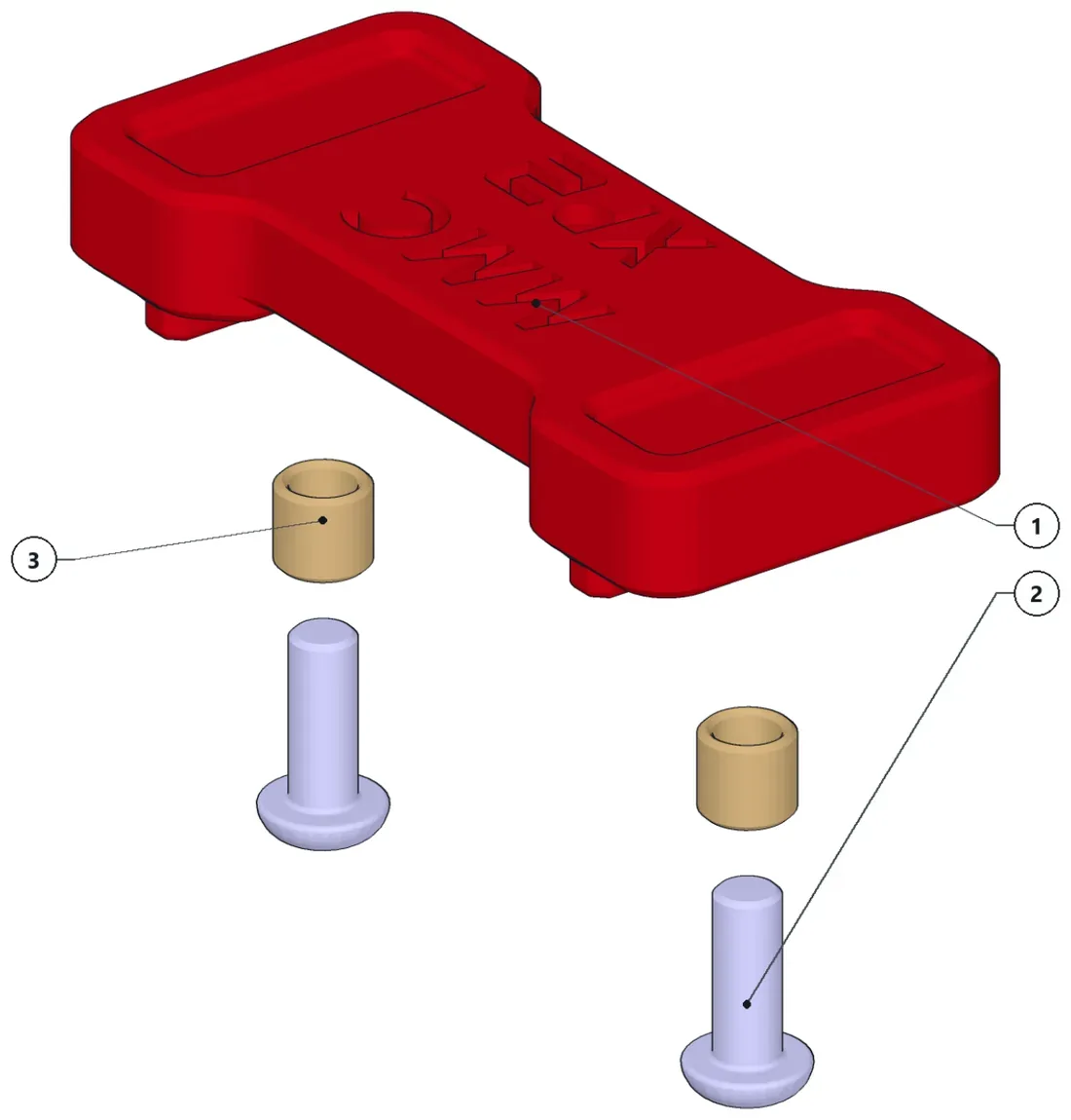
- Install the threaded inserts and keep aside to install it on the chassis’ upper deck.
Parts · numbers match the drawing
g XP2-009×1Flex plate1807380 M3x8×2ButtonHead M3x8 screwTl×2
-
Step 33: Yokomo rear axles (Y2-010)
2 parts — make 2 times
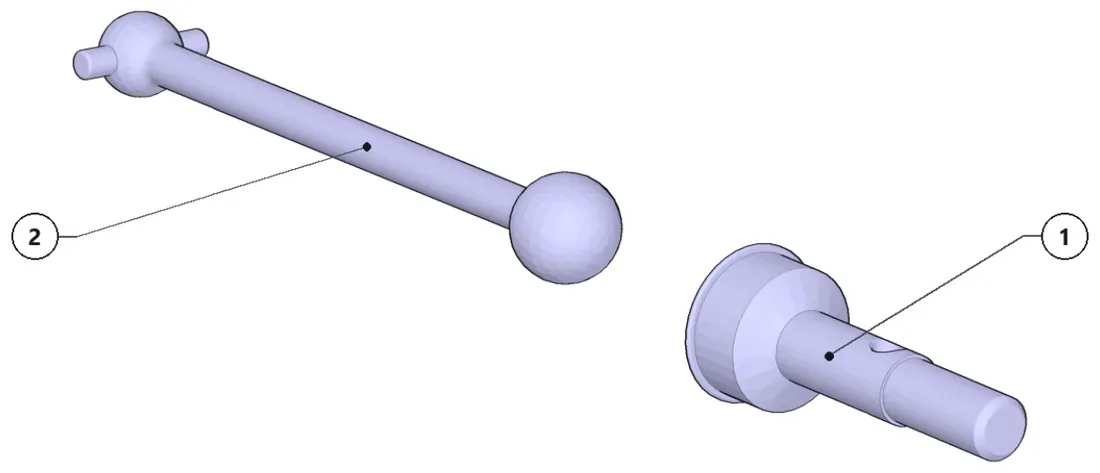
Parts · numbers match the drawing
YOKOMO_REARAXLE×1YOKOMO_47MMAXLE×1Yokomo Rear Axle (Yok…
-
Step 34: Sub-assembly XP2-1130
13 parts
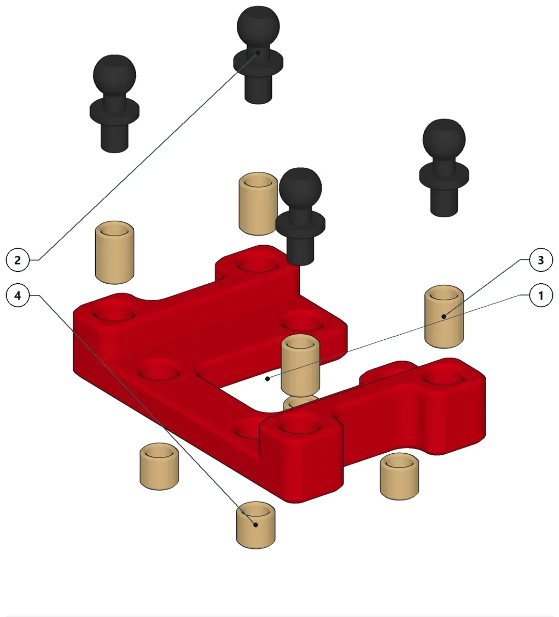
- Install all threaded inserts.
- Install the ballstuds.
Parts · numbers match the drawing
XP1-005×1BallJoint_4.8mm×44.8mm BallJoint (6mm thread)Tl6×4Th4×4
-
Step 35: Suspension front II
XP2-1100· 19 parts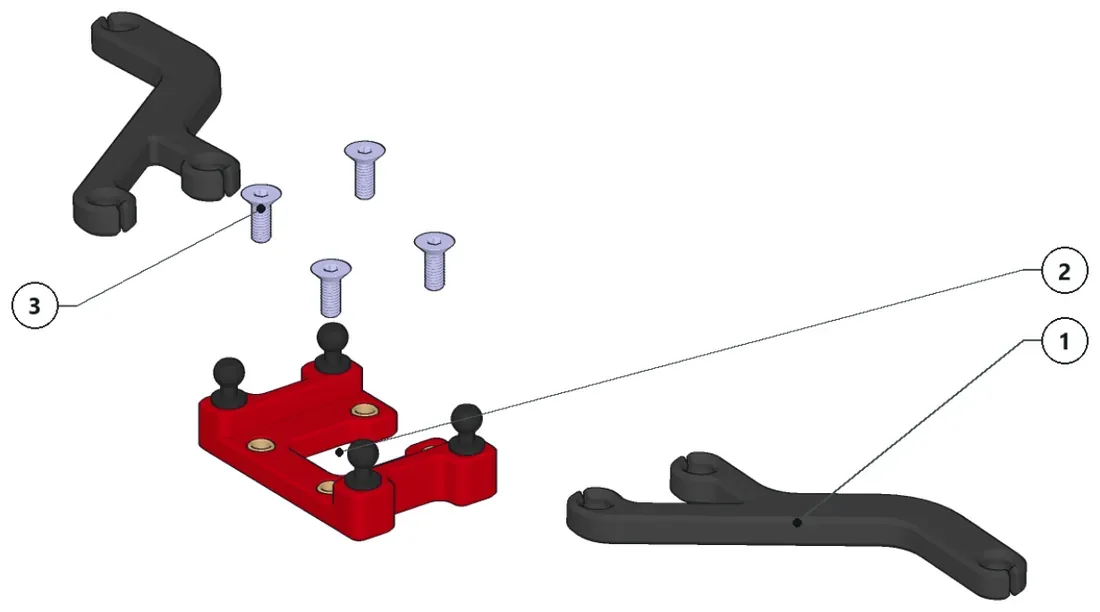
- Pop in the upper arms to the ballstuds and keep to install it to the upper deck.
Parts · numbers match the drawing
XP1-006×2XP2-1130×1ISO10642 M3x8×4CounterSunk ISO10642 M3x8…
-
Step 36: 55 mm shock absorbers
2 parts — make 4 times
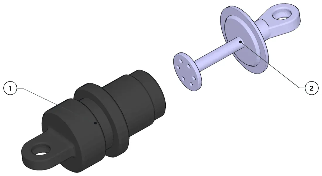
Parts · numbers match the drawing
Shock_Top×1Shock Absorber (Top Part)Shock_Bottom×1Shock Absorbers (Bottom Part)
-
Step 37: Final assembly
All sub-assemblies and loose hardware in place
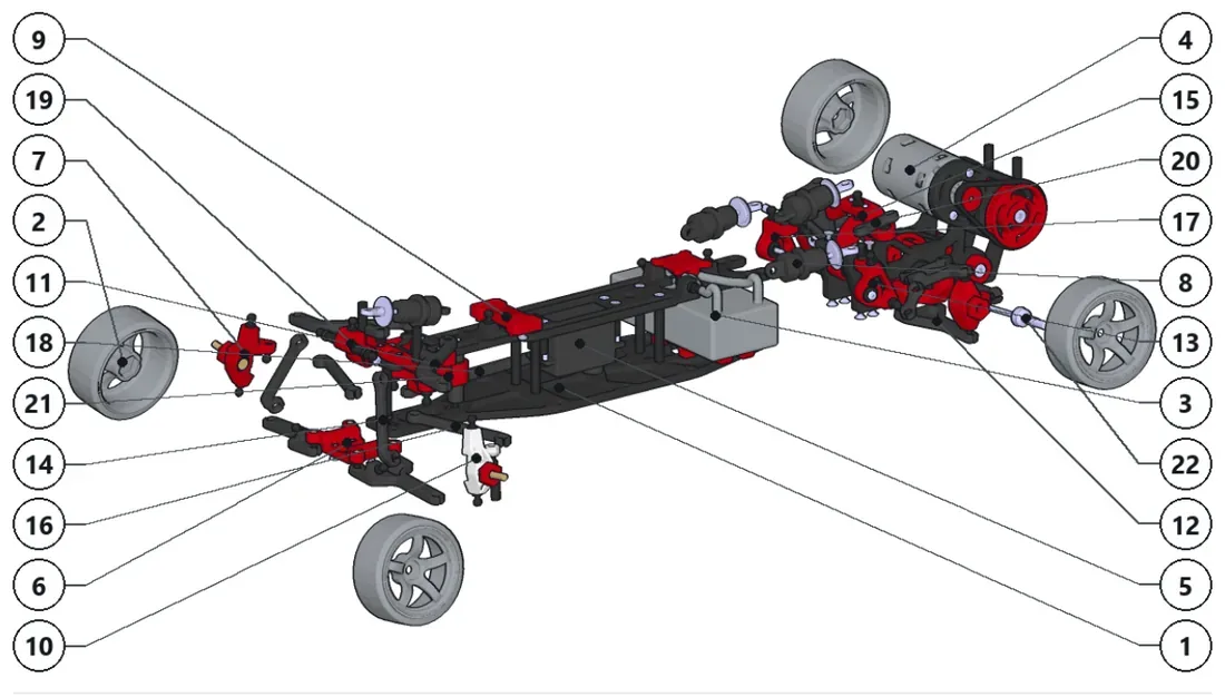
Parts · numbers match the drawing
XP2-1000_Chassis×1XP2 Structural ChassisWheels×4Battery×1"Shorty" type batteryXP2-1400_DriveTrain×1XP2-1350_Servo×1XP2-1100_Suspension_Front_|×1XP2-1150-1_FrontKnuckle_R×155mm Shock Absorber×4XP2-1160_FlexAdjustment×1XP2-1150-2_FrontKnuckle_L×1XP2-1100_Suspension_Front_ll×1XP2-1200_Suspension_Rear_|×1XP2-1240-2_RearBellCrank×1XP2-008×2Front Fixed-lenght Push-rodXP2-1240_RearHeaveCrank×1XP2-1315×2Fixed-length Steering RodsXP2-1240-1_RearBellCrank×1XP2-1311×1Servo Fixed-lenght ActuatorXP2-1140_FrontBellCrank×1XP2-1234×4Rear Traction Fixed-length ArmXP2-1300_Steering×1YOKOMO_47MMAXLE×2Yokomo Rear Axle (Yok…
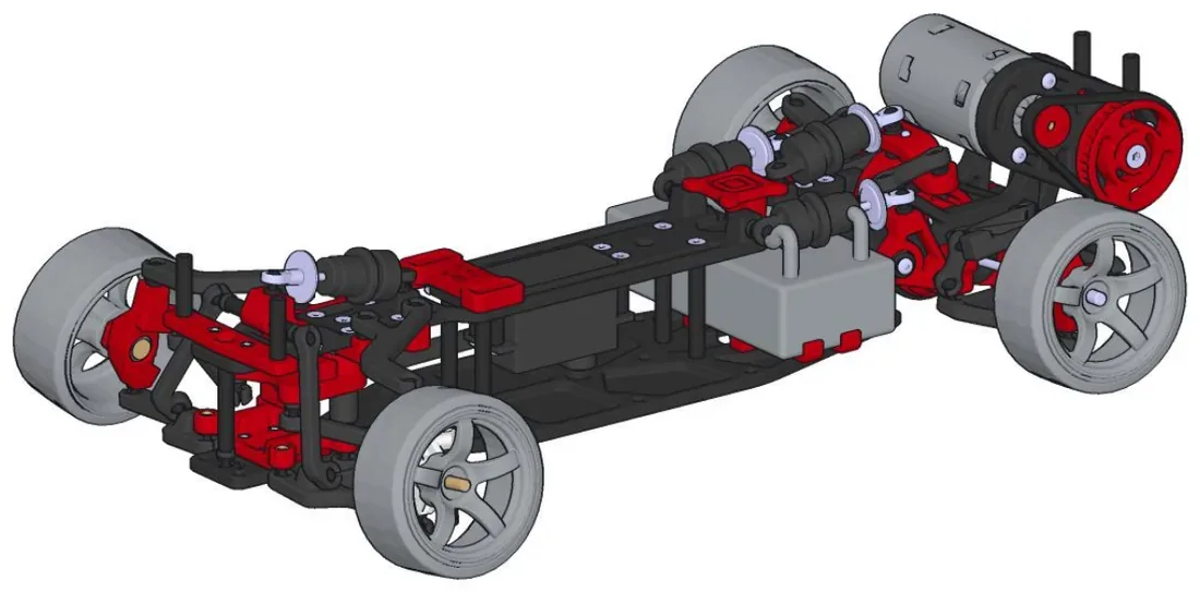
Assembled
Manual history
| V1.1.1 | Added assembly instructions. |
|---|---|
| V1.1 | Modifications to suit the RDX spool, minor pulley geometry update. |
| V1.0 | First release. |
Previous manuals (1)
- Manual V1.0 PDF, 0.9 MB